In
physics,
coherence is a property of
waves that enables stationary (i.e. temporally and spatially constant)
interference. More generally, coherence describes all properties of the
correlation between
physical quantities of a wave.
When interfering, two waves can add together to create a larger wave (
constructive interference) or subtract from each other to create a smaller wave (
destructive interference), depending on their relative
phase. Two waves are said to be coherent if they have a constant relative phase. The
degree of coherence is measured by the
interference visibility, a measure of how perfectly the waves can cancel due to destructive interference.
[edit]Introduction
Coherence was originally introduced in connection with
Thomas Young's
double-slit experiment in
optics but is now used in any field that involves waves, such as
acoustics,
electrical engineering,
neuroscience, and
quantum mechanics. The property of coherence is the basis for commercial applications such as
holography, the
Sagnacgyroscope,
radio antenna arrays,
optical coherence tomography and telescope interferometers (
astronomical optical interferometers and
radio telescopes).
[edit]Coherence and correlation
The coherence of two waves follows from how well correlated the waves are as quantified by the
cross-correlation function.
[1][2][3][4][5] The cross-correlation quantifies the ability to predict the value of the second wave by knowing the value of the first. As an example, consider two waves perfectly correlated for all times. At any time, if the first wave changes, the second will change in the same way. If combined they can exhibit complete constructive interference/superposition at all times, then it follows that they are perfectly coherent. As will be discussed below, the second wave need not be a separate entity. It could be the first wave at a different time or position. In this case, the measure of correlation is the
autocorrelation function (sometimes called
self-coherence). Degree of correlation involves correlation functions.
[edit]Examples of wave-like states
These states are unified by the fact that their behavior is described by a
wave equation or some generalization thereof.
In most of these systems, one can measure the wave directly. Consequently, its correlation with another wave can simply be calculated. However, in optics one cannot measure the
electric field directly as it oscillates much faster than any detector’s time resolution.
[6] Instead, we measure the
intensity of the light. Most of the concepts involving coherence which will be introduced below were developed in the field of optics and then used in other fields. Therefore, many of the standard measurements of coherence are indirect measurements, even in fields where the wave can be measured directly.
[edit]Temporal coherence

Figure 1: The amplitude of a single frequency wave as a function of time
t (red) and a copy of the same wave delayed by τ(green). The coherence time of the wave is infinite since it is perfectly correlated with itself for all delays τ.
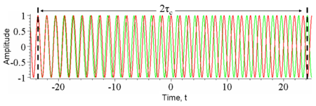
Figure 2: The amplitude of a wave whose phase drifts significantly in time τ
c as a function of time
t (red) and a copy of the same wave delayed by 2τ
c(green). At any particular time t the wave can interfere perfectly with its delayed copy. But, since half the time the red and green waves are in phase and half the time out of phase, when averaged over t any interference disappears at this delay.
Temporal coherence is the measure of the average correlation between the value of a wave and itself delayed by τ, at any pair of times. Temporal coherence tells us how monochromatic a source is. In other words, it characterizes how well a wave can interfere with itself at a different time. The delay over which the phase or amplitude wanders by a significant amount (and hence the correlation decreases by significant amount) is defined as the
coherence timeτc. At τ=0 the degree of coherence is perfect whereas it drops significantly by delay
τc. The
coherence lengthLc is defined as the distance the wave travels in time τ
c.
One should be careful not to confuse the coherence time with the time duration of the signal, nor the coherence length with the coherence area (see below).
[edit]The relationship between coherence time and bandwidth
It can be shown that the faster a wave decorrelates (and hence the smaller τ
c is) the larger the range of frequencies Δf the wave contains. Thus there is a tradeoff:
 .
.
Formally, this follows from the
convolution theorem in mathematics, which relates the
Fourier transform of the power spectrum (the intensity of each frequency) to its
autocorrelation.
[edit]Examples of temporal coherence
We consider four examples of temporal coherence.
- A wave containing only a single frequency (monochromatic) is perfectly correlated at all times according to the above relation. (See Figure 1)
- Conversely, a wave whose phase drifts quickly will have a short coherence time. (See Figure 2)
- Similarly, pulses (wave packets) of waves, which naturally have a broad range of frequencies, also have a short coherence time since the amplitude of the wave changes quickly. (See Figure 3)
- Finally, white light, which has a very broad range of frequencies, is a wave which varies quickly in both amplitude and phase. Since it consequently has a very short coherence time (just 10 periods or so), it is often called incoherent.
The most monochromatic sources are usually
lasers; such high monochromaticity implies long coherence lengths (up to hundreds of meters). For example, a stabilized
helium-neon laser can produce light with coherence lengths in excess of 5 m. Not all lasers are monochromatic, however (e.g. for a mode-locked
Ti-sapphire laser, Δλ ≈ 2 nm - 70 nm). LEDs are characterized by Δλ ≈ 50 nm, and tungsten filament lights exhibit Δλ ≈ 600 nm, so these sources have shorter coherence times than the most monochromatic lasers.
Holography requires light with a long coherence time. In contrast,
Optical coherence tomography uses light with a short coherence time.
[edit]Measurement of temporal coherence

Figure 3: The amplitude of a wavepacket whose amplitude changes significantly in time τ
c (red) and a copy of the same wave delayed by 2τ
c(green) plotted as a function of time
t. At any particular time the red and green waves are uncorrelated; one oscillates while the other is constant and so there will be no interference at this delay. Another way of looking at this is the wavepackets are not overlapped in time and so at any particular time there is only one nonzero field so no interference can occur.

Figure 4: The time-averaged intensity (blue) detected at the output of an interferometer plotted as a function of delay τ for the example waves in Figures 2 and 3. As the delay is changed by half a period, the interference switches between constructive and destructive. The black lines indicate the interference envelope, which gives the
degree of coherence. Although the waves in Figures 2 and 3 have different time durations, they have the same coherence time.
In optics, temporal coherence is measured in an interferometer such as the
Michelson interferometer or
Mach–Zehnder interferometer. In these devices, a wave is combined with a copy of itself that is delayed by time τ. A detector measures the time-averaged
intensity of the light exiting the interferometer. The resulting interference visibility (e.g. see Figure 4) gives the temporal coherence at delay τ. Since for most natural light sources, the coherence time is much shorter than the time resolution of any detector, the detector itself does the time averaging. Consider the example shown in Figure 3. At a fixed delay, here 2τ
c, an infinitely fast detector would measure an intensity that fluctuates significantly over a time
t equal to τ
c. In this case, to find the temporal coherence at 2τ
c, one would manually time-average the intensity.
[edit]Spatial coherence
In some systems, such as water waves or optics, wave-like states can extend over one or two dimensions. Spatial coherence describes the ability for two points in space,
x1 and
x2, in the extent of a wave to interfere, when averaged over time. More precisely, the spatial coherence is the
cross-correlation between two points in a wave for all times. If a wave has only 1 value of amplitude over an infinite length, it is perfectly spatially coherent. The range of separation between the two points over which there is significant interference is called the coherence area,
Ac. This is the relevant type of coherence for the Young’s double-slit interferometer. It is also used in optical imaging systems and particularly in various types of astronomy telescopes. Sometimes people also use “spatial coherence” to refer to the visibility when a wave-like state is combined with a spatially shifted copy of itself.
[edit]Examples of spatial coherence
- Spatial coherence
Figure 6: A wave with a varying profile (wavefront) and infinite coherence length.
Figure 7: A wave with a varying profile (wavefront) and finite coherence length.
Figure 8: A wave with finite coherence area is incident on a pinhole (small aperture). The wave will diffract out of the pinhole. Far from the pinhole the emerging spherical wavefronts are approximately flat. The coherence area is now infinite while the coherence length is unchanged. Figure 9: A wave with infinite coherence area is combined with a spatially-shifted copy of itself. Some sections in the wave interfere constructively and some will interfere destructively. Averaging over these sections, a detector with length D will measure reduced interference visibility. For example a misaligned Mach–Zehnder interferometer will do this.
Consider a tungsten light-bulb filament. Different points in the filament emit light independently and have no fixed phase-relationship. In detail, at any point in time the profile of the emitted light is going to be distorted. The profile will change randomly over the coherence time
τc. Since for a white-light source such as a light-bulb
τc is small, the filament is considered a spatially incoherent source. In contrast, a radio
antenna array, has large spatial coherence because antennas at opposite ends of the array emit with a fixed phase-relationship. Light waves produced by a laser often have high temporal and spatial coherence (though the degree of coherence depends strongly on the exact properties of the laser). Spatial coherence of laser beams also manifests itself as speckle patterns and diffraction fringes seen at the edges of shadow.
Holography requires temporally and spatially coherent light. Its inventor,
Dennis Gabor, produced successful holograms more than ten years before lasers were invented. To produce coherent light he passed the monochromatic light from an emission line of a
mercury-vapor lamp through a pinhole spatial filter.
In February 2011, Dr
Andrew Truscott, leader of a research team at the ARC Centre of Excellence for Quantum-Atom Optics at
Australian National University in
Canberra, Australian Capital Territory, showed that
helium atoms cooled to near
absolute zero /
Bose-Einstein condensate state, can be made to flow and behave as a coherent beam as occurs in a laser.
[7][8]
[edit]Spectral coherence

Figure 10: Waves of different frequencies (i.e. colors) interfere to form a pulse if they are coherent.

Figure 11: Spectrally incoherent light interferes to form continuous light with a randomly varying phase and amplitude
Waves of different frequencies (in light these are different colours) can interfere to form a pulse if they have a fixed relative phase-relationship (see
Fourier transform). Conversely, if waves of different frequencies are not coherent, then, when combined, they create a wave that is continuous in time (e.g. white light or
white noise). The temporal duration of the pulse
Δt is limited by the spectral bandwidth of the light
Δf according to:
 ,
,
which follows from the properties of the Fourier transform (for quantum particles it also results in the
Heisenberg uncertainty principle).
If the phase depends linearly on the frequency (i.e.

) then the pulse will have the minimum time duration for its bandwidth (a
transform-limited pulse), otherwise it is chirped (see
dispersion).
[edit]Measurement of spectral coherence
Measurement of the spectral coherence of light requires a
nonlinear optical interferometer, such as an intensity
optical correlator,
frequency-resolved optical gating (FROG), or
Spectral phase interferometry for direct electric-field reconstruction (SPIDER).
[edit]Polarization coherence
Light also has a
polarization, which is the direction in which the electric field oscillates. Unpolarized light is composed of two equally intense incoherent light waves with orthogonal polarizations. The electric field of the unpolarized light wanders in every direction and changes in phase over the coherence time of the two light waves. A
polarizer rotated to any angle will always transmit half the incident intensity when averaged over time.
If the electric field wanders by a smaller amount the light will be partially polarized so that at some angle, the polarizer will transmit more than half the intensity. If a wave is combined with an orthogonally polarized copy of itself delayed by less than the coherence time, partially polarized light is created.
The polarization of a light beam is represented by a vector in the
Poincare sphere. For polarized light the end of the vector lies on the surface of the sphere, whereas the vector has zero length for unpolarized light. The vector for partially polarized light lies within the sphere
[edit]Applications
[edit]Holography
Coherent superpositions of
optical wave fields include
holography. Holographic objects are used frequently in daily life in bank notes and credit cards.